Smart Grid Ready Instrumentation
Overview
Critical Components for Smart Grid Ready Instrumentation
There is no silver bullet when it comes to smart grid implementation, and it is likely to be an ongoing global effort for years to come that will require multiple iterations wit constantly evolving requirements. On one side, stand-alone traditional instruments such as reclosers, power-quality meters, transient recorders, and phasor measurement units are robust, standards-based, and embedded – but are designed to perform one or more specific/fixed tasks defined by the vendor (i.e. the user generally cannot extend or customize them). In addition, special technologies and costly components must be developed to build these instruments, making them very expensive and slow to adapt. On the other side, the rapid adoption of the PC in the last 30 years catalyzed a revolution in instrumentation for test, measurement, and automation. Computers are powerful, open-source, I/O expandable, and programmable, but not robust and not embedded enough for field deployment.
One major development resulting from the ubiquity of the PC is the concept of virtual instrumentation, which offers several benefits to engineers and scientists who require increased productivity, accuracy, and performance. Virtual instrumentation bridges traditional instrumentation with computers offering the best of both worlds: measurement and quality, embedded processing power, reliability and robustness, open-source programmability, and field-upgradability.
Virtual Instrumentation
Virtual instrumentation is the foundation for smart grid-ready instrumentation. Engineers and scientists working on smart grid applications where needs and requirements change very quickly; need flexibility to create their own solutions. Virtual instruments, by virtue of being PC-based, inherently take advantage of the benefits from the latest technology incorporated into off-the-shelf PCs, and they can be adapted via software and plug-in hardware to meet particular application needs without having to replace the entire device.
While software tools provide the programming environment to customize the functionality of a smart grid-ready instrument, there is a need for an added layer of robustness and reliability that a standard off-the-shelf PC cannot offer. One of the most empowering technologies that add this required level of reliability, robustness and performance is the Field Programmable Gate Array (FPGA) technology.
FGPAs
At the highest level, FPGAs are reprogrammable silicon chips. Using prebuilt logic blocks and programmable routing resources, you can configure these chips to implement custom hardware functionality without ever having to pick up a breadboard or soldering iron. You develop digital computing tasks in software and compile them down to a configuration file or bitstream that contains information on how the components should be wired together. In addition, FPGAs are completely reconfigurable and instantly take on a brand new “personality” when you recompile a different configuration of circuitry. In the past, FPGA technology was only available to engineers with a deep understanding of digital hardware design. The rise of high-level design tools, however, is changing the rules of FPGA programming, with new technologies that convert graphical block diagrams or even C code into digital hardware circuitry (Fig. 1).
Fig. 1: Graphical FPGA design translated to independent parts of an FPGA.
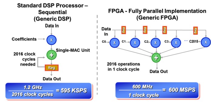
FPGA chip adoption across all industries is driven by the fact that FPGAs combine the best parts of ASICs and processor-based systems. FPGAs provide hardware-timed speed and reliability, but they do not require high volumes to justify the large upfront expense of custom ASIC design. Reprogrammable silicon also has the same flexibility of software running on a processor-based system, but it is not limited by the number of processing cores available. Unlike processors, FPGAs are truly parallel in nature so different processing operations do not have to compete for the same resources. Each independent processing task is assigned to a dedicated section of the chip, and can function autonomously without any influence from other logic blocks. As a result, the performance of one part of the application is not affected when additional processing is added (Fig. 2).
Fig. 2: Sequential vs. parallel implementation of a tap filter utilizing an FPGA with 2016 DSP slices at 600 million samples per second (MSPS).
FPGA circuitry is truly a “hard” implementation of program execution. Processor-based systems often involve several layers of abstraction to help schedule tasks and share resources among multiple processes. The driver layer controls hardware resources and the operating system manages memory and processor bandwidth. For any given processor core, only one instruction can execute at a time, and processor-based systems are continually at risk of time-critical tasks pre-empting one another. FPGAs, which do not use operating systems, minimize reliability concerns with true parallel execution and deterministic hardware dedicated to every task. Taking advantage of hardware parallelism, FPGAs exceed the computing power of computer processors and digital signal processors (DSPs) by breaking the paradigm of sequential execution and accomplishing more per clock cycle.
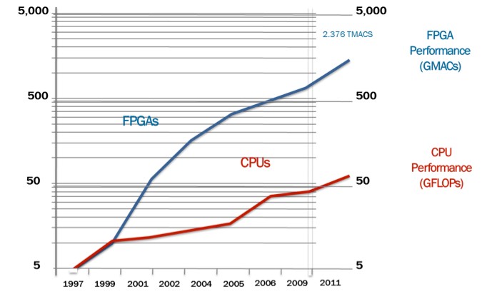
Moore’s law has driven the processing capabilities of microprocessors and multicore architectures on those chips continue to push this curve higher (Fig. 3). BDTI, a noted analyst and benchmarking firm, released benchmarks showing how FPGAs can deliver many times the processing power per dollar of a DSP solution in some applications [2]. Controlling inputs and outputs (I/O) at the hardware level provides faster response times and specialized functionality to closely match application requirements.
Fig. 3: Moore’s law comparing FPGA and CPU performance.
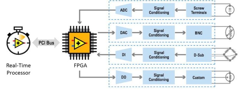
The incredible parallel processing of an FPGA has enabled to scale at a similar rate, while optimized for different types of calculations. The best architectures take advantage of both these technologies (Fig. 4).
Fig. 4: Processor + FPGA combined architecture.
As mentioned earlier, FPGA chips are field-upgradable and do not require the time and expense involved with ASIC redesign. Digital communication protocols, for example, have specifications that can change over time, and ASIC-based interfaces may cause maintenance and forward compatibility challenges. Being reconfigurable, FPGA chips are able to keep up with future modifications that might be necessary. As a product or system matures, you can make functional enhancements without spending time redesigning hardware or modifying the board layout.
NI CompactRIO Platform
The National Instruments compactRIO platform leverages the FPGA technology and offers high reliability and performance without compromising flexibility. CompactRIO C Series I/O modules provide interfaces to the outside world, and the RT processor augments this architecture with high performance analysis and control capabilities. The system is programmed utilizing NI LabVIEW Graphical System Design platform, and it can be customized as well as upgraded in the field, without changing the hardware, to behave as a number of different “personalities”, such as PMU, Power Quality, Smart Switch, Recloser, etc. The NI compactRIO is the ideal approach for smart grid applications that demands evolving functionality and requirements.
NI-based PMU Solution
The PMU solution based on the National Instruments CompactRIO platform, allows operators and engineers to gain grid condition visibility, situational awareness, event analysis, and the ability to take corrective action to ensure a reliable electric network. This enables a wide range of applications and can bring significant financial benefits such as:
• Operational efficiency
• Improved asset management
• Minimize regulatory risk
• Informed decision making
The benefits of using PMU technology enable utilities to proactively plan and prevent deviations in the delivery of energy. The PMU instrumentation based of NI compactRIO technology is designed to meet requirements for reliability, interoperability, extreme environmental conditions suitable for substation or pole mount, and advanced algorithms for event and system analysis.
Key features include:
• High performance based on intel core i7 processors supporting advanced real-time analytics
• High fidelity ADCs with 24-bits of resolution
• Dual-Ethernet, serial ports and digital communication
• Acquisition rates up to 833 samples/cycle
• Data transfer configurable up to 240 messages per second
• Multichannel synchrophasors with scalable mixed I/O (AI, AO, Digital)
• Data packages based on IEEE C37.118-2011
• Simultaneous multiple protocols TCP/IP, DNP3, Modbus RTU, IEC-60870, IEC 61850
• PMU and power quality algorithms in one unit
• Rugged design: -40 to 70 C
Solution Implementation
Distributed systems such as PMUs, or distributed intelligence is not a novel concept. For mathematicians, it may be farming out computing tasks to a computer grid. Business executives may think of Web-based commerce systems globally processing orders. Facilities managers may imagine wireless sensor networks monitoring the health of a building. All of these examples, however, share a fundamental theme – a distributed system is any system that uses multiple processors/nodes to solve a problem. Because of the tremendous cost and performance improvements in FPGA technology, and its applications to build smart grid-ready instrumentation described previously, power engineers are finding more effective ways to meet smart grid application challenges by adding more computing engines/nodes to smart grid systems.
Distributed intelligence promotes optimum network response times and bandwidth utilization, allows unprecedented amounts of data and grid control operations to be seamlessly managed through the system without clogging wireless networks, and enhances reliability through decentralized coordination instead of through the imposition of hierarchical control via a central SCADA system. However, designing multiple computing engines into a smart grid control system, and later managing those systems has not been as easy as engineers might hope.
Developing distributed systems introduces an entirely new set of programming challenges that traditional tools do not properly address. It requires unique programming approaches. For instance, in a sensor network, wireless sensors are self-organizing units that organically connect to other sensors in the vicinity to build a communication fabric. In another example, grid monitoring systems feature remotely distributed, headless reclosers, power quality meters, circuit breakers, PMUs, etc. that monitor and control different grid conditions while logging data to SCADA databases. The challenges engineers and scientists face in developing distributed systems include (1) programming applications that take advantage of multiple processors/nodes based on the same or mixed architectures, (2) sharing data efficiently among multiple processors/nodes that are either directly connected on a single PCB or box or remotely connected on a network, (3) coordinating all nodes as a single system, including the timing and synchronization between nodes, (4) integrating different types of I/O such as high-speed digital, analog waveforms, phasor measurement measurements, (5) incorporating additional services to the data shared between nodes, such as logging, alarming, remote viewing, and integration with enterprise SCADA systems.
Fig. 5: Distributed systems can range from systems physically located in a single box or remote systems remotely distributed in separate devices or systems on a network.
The following sub-sections discuss key technologies and approaches to mitigate the new challenges introduced by distributed intelligence applications.
A. Graphical System Design
These advanced concepts are not commonplace in the power industry yet, but common in other demanding industries such as military/aero, automotive, oil and gas. With the introduction of Graphical System Design tools, such as National Instruments LabVIEW that leverage the data flow paradigm, the complexity of such concepts can be abstracted at a higher level facilitating application and system development. In the data flow paradigm, a program node executes when it receives all required inputs. When a node executes, it produces output data and passes the data to the next node in the dataflow path. The movement of data through the nodes determines the execution order of the VIs and functions on the block diagram. Visual Basic, C++, JAVA, and most other text-based programming languages follow a control flow model of program execution. In control flow, the sequential order of program elements determines the execution order of a program. For a dataflow programming example, consider a block diagram that adds two numbers and then subtracts 50.00 from the result of the addition, as shown in Figure 6. In this case, the block diagram executes from left to right, not because the objects are placed in that order, but because the Subtract function cannot execute until the Add function finishes executing and passes the data to the Subtract function. Remember that a node executes only when data are available at all of its input terminals and supplies data to the output terminals only when the node finishes execution.
Fig. 6: Dataflow Programming Example
The Graphical System Design approach addresses those programming challenges by providing the tools to program dissimilar nodes from a single development environment using a block diagram approach engineers and scientists are familiar with. Engineers can then develop code to run on computing devices ranging from desktop PCs, embedded controllers, FPGAs, and DSPs utilizing the same development environment. The ability of one tool to transcend the boundaries of node functionality dramatically reduces the complexity and increases the efficiency of distributed application development.
B. Communication and Data Transfer
Distributed systems also requires various forms of communication and data sharing. Addressing communication needs between often functionally different nodes is challenging. While various standards and protocols exist for communication – such as DNP3, IEC 60870, IEC 61850, TCP/IP, Modbus TCP, OPC – one protocol cannot usually meet all of an engineer’s needs, and each protocol has a different API. This forces engineers designing distributed systems to use multiple communication protocols to complete the entire system. For deterministic data transfer between nodes, engineers are often forced to use complex and sometimes expensive solutions based on technologies such as reflective memory, EtherCAT, C37.118, and IEC 61850 GOOSE/SMV. In addition, any communication protocol or system an engineer uses also must integrate with existing enterprise SCADA systems. One way to address these often competing needs is to abstract the specific transport layer and protocol. By doing this, engineers can use multiple protocols under the hood, unify the code development, and dramatically save development time. Once more Graphical System Design tools address these challenges with flexible, open communication interfaces that provides data sharing among multiple device nodes (for example, a circuit breaker and a recloser) and integrates with SCADA systems.
C. Synchronizing the System across Multiple Nodes
Another important component of many distributed systems is coordination and synchronization across intelligent nodes of a network. For many grid control systems, the interface to the external system is through I/O – sensors, actuators, or direct electronic signals. Traditional instruments connected through GPIB, USB, or Ethernet to a computer can be considered a node on a distributed system because the instruments provide in-box processing and analysis using a processor. However, the system developer may not have direct access to the inner workings of a traditional instrument, making it difficult to optimize the performance of the instrument within the context of an entire system.
Through virtual instrumentation platforms – such as National Instruments CompactRIO, which is based on chassis with backplanes and user-selectable modules – engineers have more options for synchronization and control. National Instruments LabVIEW provides fast development for FPGA-based reconfigurable I/O (RIO) devices and tight integration with dedicated circuitry for synchronizing multiple devices to act as one for distributed and high-channel-count applications. Engineers can extend compactRIO chassis backplanes across multiple chassis to share timing and trigger signals using a varety of techniques including IEEE 1588, high-speed digital lines or built-in GPS receivers to implement advanced multi-device synchronization.
D. Navigate, Debug, and Deploy Code to Distributed Nodes
Moving data and commands among different computing nodes in a distributed system is only one of the challenges involved in developing a distributed system. Managing and deploying the source that runs on these distributed nodes is a fundamental challenge faced by system developers. In the simplest distributed case, where homogenous computing nodes execute the exact same source code, engineers can maintain the master source in one place and then distribute it to all nodes when they alter the code. In the advanced distributed case, each node has dissimilar executable code running on mixed architectures, and all nodes may not be online simultaneously.
A Graphical System Design environment such as NI LabVIEW can be used to manage the source code and application distribution for an entire system of computing nodes from one environment.
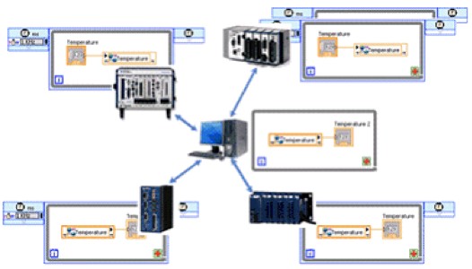
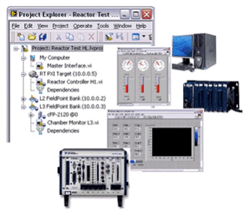
Fig. 7: The LabVIEW project stores the source code and settings for all nodes in a distributed system, including: PCs, real-time controllers, FPGA processors, and handheld devices.
With NI LabVIEW, developers can significantly simplify the entire system development. All real-time, FPGA, and handheld devices in the system are visible in the LabVIEW project, making it easy for developers to manage the system. Developers can add targets to the project even if they are off line, making it simpler to design the architecture and develop the system when some components are missing. From an intuitive tree view in the project, developers can view, edit, redeploy, execute, and debug code running on any node in the system. Developers can observe the interaction among all the distributed system nodes in real time, which is critical because intelligent nodes can execute simultaneously. This ability improves communication and synchronization design, development, and debugging, as well as reducing overall development time significantly.
Additional Resources
- Download the PMU Resource Kit
- Learn more about CompactRIO
- View the NI Electrical Power Suite
- Explore reasons for choosing NI for choosing NI for microgrid and distributed generation control
- Learn more about NI grid automation systems
- Watch a webinar about testbed platforms for smart grid and microgrid research
- See a video about controlling and monitoring microgrids

